
xnx xnx transmitter installation manual
XNX Universal Transmitter Installation Manual: A Comprehensive Plan

This manual details the installation of the XNX Universal Transmitter‚ covering safety‚ components‚ wiring‚ and configuration for optimal performance and reliable gas detection․
The Honeywell XNX Universal Transmitter is a versatile and powerful device designed for a wide range of gas detection applications․ It seamlessly integrates with various sensor technologies‚ offering exceptional flexibility and performance․ This transmitter supports multiple communication protocols‚ enabling easy integration into existing control systems․
Its robust construction and advanced features ensure reliable operation in harsh environments․ The XNX is engineered for simple installation and configuration‚ minimizing downtime and maximizing efficiency․ This manual provides comprehensive guidance for installing‚ configuring‚ and maintaining the XNX Universal Transmitter‚ ensuring optimal performance and long-term reliability․ Understanding its capabilities is key to a successful deployment․
Safety Precautions & Warnings
Prior to installing or servicing the XNX Universal Transmitter‚ carefully review all safety information․ Electrical shock hazard exists – disconnect power before working with wiring․ Ensure proper grounding to prevent dangerous voltages․
Avoid installation in hazardous locations without appropriate certifications․ Use intrinsically safe tools and follow all local and national electrical codes․ Never attempt to repair the transmitter yourself; contact qualified personnel for service․ Failure to adhere to these precautions could result in personal injury or equipment damage․ Always wear appropriate personal protective equipment (PPE) during installation and maintenance procedures․
Unpacking and Inspection
Upon receiving the XNX Universal Transmitter‚ carefully inspect the shipping container for any signs of damage․ If damage is evident‚ immediately file a claim with the carrier․ Once opened‚ verify that all components listed on the packing slip are present․
Inspect the transmitter unit itself for any physical damage‚ such as cracks or dents․ Check all included accessories – mounting hardware‚ sensors (if applicable) – for completeness and condition․ Do not install a damaged or incomplete unit․ Contact Honeywell support immediately to report any discrepancies or issues found during the unpacking and inspection process․
System Components Overview
The XNX Universal Transmitter system comprises several key components working in unison for accurate gas detection․ This includes the core Transmitter Unit itself‚ designed for versatile sensor integration․ Compatibility extends to a wide range of Sensor Technologies‚ enabling detection of various gases․
Essential for secure installation are the included Mounting Accessories‚ providing options for diverse environments․ The transmitter features five conduit entries for flexible wiring․ Understanding each component’s role is crucial for a successful installation and ongoing operation․ Proper integration ensures reliable performance and long-term system integrity․
Transmitter Unit
The XNX Universal Transmitter unit serves as the central hub for gas detection‚ processing signals from connected sensors․ Its robust housing‚ featuring five integrated conduit entries‚ facilitates easy wiring and mounting․ This unit supports diverse sensor technologies‚ offering flexibility in application․
Internally‚ the transmitter houses sophisticated circuitry for signal conditioning and communication․ It’s designed for reliable operation in harsh industrial environments․ Configuration is achieved through established communication protocols‚ allowing seamless integration into existing systems․ The unit’s compact design and versatile features make it a cornerstone of any comprehensive gas detection strategy․

Sensor Technologies Compatibility
The XNX Universal Transmitter boasts broad compatibility with a wide array of sensor technologies‚ enhancing its versatility․ It readily integrates with electrochemical‚ infrared‚ and catalytic bead sensors‚ catering to diverse gas detection needs․ Specifically‚ it supports mV remote sensors‚ allowing for flexible mounting configurations and extended coverage․
Thread type considerations are crucial for secure sensor connections; the transmitter accommodates various standard thread types․ This compatibility ensures accurate and reliable gas measurements across numerous applications․ The XNX’s adaptability simplifies system design and reduces the need for specialized equipment‚ providing a cost-effective solution for comprehensive gas monitoring․
Mounting Accessories
The XNX Universal Transmitter is designed for flexible installation‚ utilizing a range of mounting accessories to suit diverse environments․ These include wall mounting brackets‚ conduit adapters‚ and swivel mounts‚ ensuring secure and stable placement․ The transmitter housing features five integrated cable/conduit entries‚ simplifying wiring and sensor connections․
Proper selection of mounting hardware is critical for long-term reliability․ Accessories are constructed from durable‚ corrosion-resistant materials‚ suitable for harsh industrial settings․ Detailed guidelines for accessory installation are provided within this manual‚ ensuring optimal performance and adherence to safety standards․ These components facilitate easy integration into existing infrastructure․
Pre-Installation Considerations
Before commencing installation of the XNX Universal Transmitter‚ careful consideration of potential electrical interference is crucial for accurate and reliable operation․ Wiring-induced voltage drops can significantly impact sensor readings; therefore‚ appropriate wire gauge selection is paramount․ Mitigating transient electrical noise‚ stemming from nearby equipment‚ requires proper grounding and shielding techniques․
Furthermore‚ dissimilar earth ground potentials between the transmitter and sensors can introduce errors․ Addressing this necessitates establishing a common ground reference point․ Thorough site assessment and adherence to recommended practices will ensure optimal system performance and prevent inaccurate readings‚ safeguarding personnel and processes․
Wiring-Induced Voltage Drops
Significant voltage drops along the wiring path can compromise the accuracy of the XNX Universal Transmitter’s sensor readings․ This occurs due to the resistance of the wiring itself‚ particularly over extended distances․ To mitigate this‚ utilize appropriately sized conductors – thicker gauge wires exhibit lower resistance․
Carefully calculate the total wire length and anticipated current draw to determine the correct wire gauge based on established electrical engineering principles․ Minimizing wire length whenever possible is also beneficial․ Regularly inspect wiring connections for corrosion or looseness‚ as these can exacerbate voltage drop issues and impact system reliability․
Transient Electrical Noise Mitigation
The XNX Universal Transmitter’s sensitive electronics are susceptible to interference from transient electrical noise․ Sources include nearby motors‚ radio transmitters‚ and switching power supplies․ To minimize impact‚ separate signal wiring from power cables‚ ideally running them in separate conduits or shielded cables․
Employing surge protection devices (SPDs) at the power entry point and on signal lines can effectively clamp voltage spikes․ Proper grounding is crucial; ensure a robust earth ground connection to the transmitter housing․ Consider using twisted-pair wiring for sensor signals‚ as this configuration helps cancel out induced noise․ Regularly inspect grounding connections for integrity․
Dissimilar Earth Ground Potentials
Differences in earth ground potential between the XNX Transmitter and connected sensors can induce unwanted currents‚ leading to inaccurate readings or even equipment damage․ This is particularly relevant in installations spanning different buildings or utilizing separate grounding systems․
To mitigate this‚ implement an isolation barrier‚ such as an isolation amplifier‚ in the sensor signal path․ Alternatively‚ establish a common ground point by bonding the ground conductors of all connected equipment․ Regularly measure the potential difference between ground points to verify effectiveness․ Careful planning during installation is vital to avoid ground loops and ensure signal integrity․
Mounting the XNX Transmitter
The XNX Transmitter is designed for versatile mounting‚ accommodating various installation scenarios․ Its robust housing features five integrated cable/conduit entries‚ providing flexibility for wiring and sensor connections – refer to Figure 3 for detailed guidance․ Installation options include a single transmitter setup‚ multiple units sharing a single power source‚ or a daisy-chain configuration for extended coverage․
Ensure the mounting surface is structurally sound and capable of supporting the transmitter’s weight․ Proper alignment and secure fastening are crucial for stable operation․ Consider accessibility for future maintenance and calibration when selecting the mounting location․
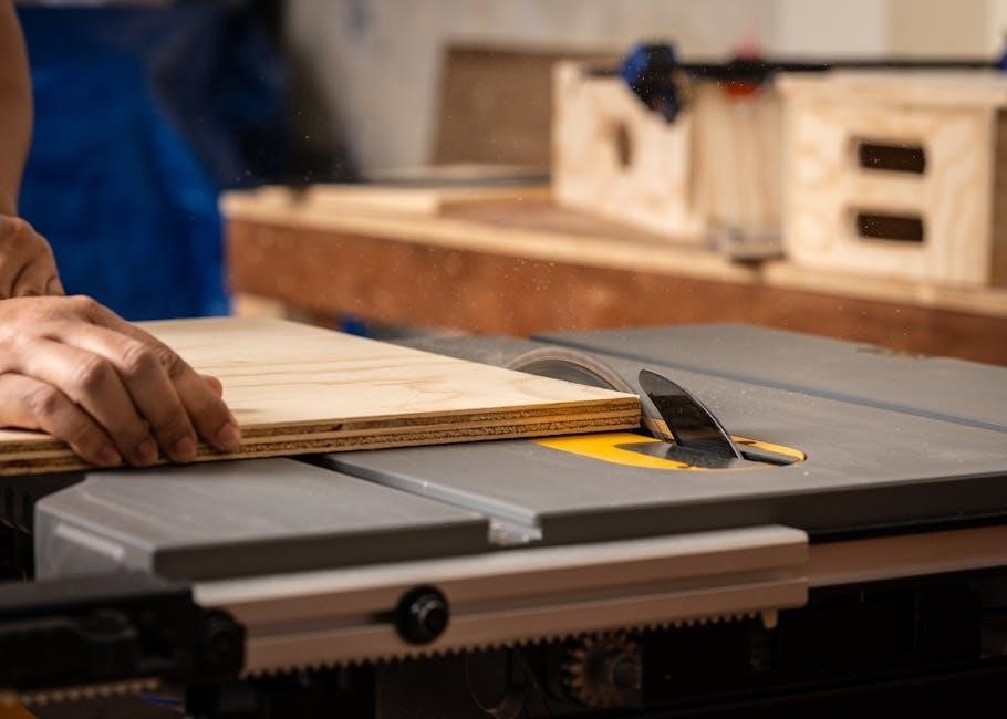
Housing and Conduit Entries (5 Entries)
The XNX Universal Transmitter housing incorporates five strategically positioned conduit entries‚ enhancing installation flexibility․ These entries accommodate various cable diameters and conduit types‚ simplifying wiring and sensor connections․ Proper sealing of unused entries is vital to maintain the enclosure’s ingress protection rating‚ safeguarding internal components from dust and moisture․
When utilizing the conduit entries‚ ensure compliance with local electrical codes and standards․ Employ appropriate cable glands or sealing fittings to prevent environmental ingress․ Careful planning of cable routing minimizes interference and facilitates easy access for maintenance and troubleshooting․
Single Transmitter Installation
For a single XNX Universal Transmitter installation‚ mount the unit securely to a suitable surface‚ ensuring adequate ventilation․ Connect the power supply‚ observing correct polarity‚ and verify the voltage matches the transmitter’s requirements․ Wire the sensor(s) according to the sensor’s datasheet and the XNX wiring diagram‚ paying close attention to signal and ground connections․
After wiring‚ perform a visual inspection to confirm all connections are secure and properly insulated․ Initiate the transmitter’s startup sequence and verify correct operation through the display and communication protocols․ This straightforward setup is ideal for localized gas detection needs․
Multiple Transmitter – Single Power Source Installation
When installing multiple XNX Universal Transmitters from a single power source‚ ensure the power supply’s capacity meets the combined current draw of all units․ Utilize a star wiring configuration‚ connecting each transmitter directly to the power source to minimize voltage drop and potential interference․ Proper grounding is crucial; connect all transmitter grounds to a common earth point․
Carefully label each transmitter and its corresponding wiring for easy identification during maintenance․ Verify individual transmitter operation after power-up‚ confirming each unit responds correctly and communicates effectively․ This configuration reduces wiring complexity but demands careful power management․
Daisy-Chain Configuration Installation
The daisy-chain installation method for XNX Universal Transmitters connects units sequentially‚ sharing power from the initial transmitter․ This approach minimizes wiring runs but requires careful consideration of voltage drop across each unit․ Ensure the lead transmitter has sufficient power capacity to support all downstream devices․
Proper termination is vital; the last transmitter in the chain must be correctly terminated to prevent signal reflection and communication errors․ Label each transmitter’s position in the chain for easy troubleshooting․ Regularly monitor voltage levels at each unit to confirm adequate power delivery and reliable operation throughout the system․
Sensor Installation & Connection
Proper sensor installation is crucial for accurate readings with the XNX Universal Transmitter․ Remote sensors offer flexibility‚ but mounting guidelines must be followed based on the specific location and sensor type․ mV remote sensors require careful wiring to minimize signal loss and noise interference․
Thread type compatibility is essential for a secure and leak-proof connection․ Always use appropriate sealing compounds and torque specifications․ Ensure sensor placement aligns with the target gas’s characteristics and potential leak sources․ Regularly inspect sensor connections for tightness and corrosion to maintain optimal performance and data integrity․
Remote Sensor Mounting Guidelines
When mounting remote sensors‚ prioritize accessibility for maintenance and calibration․ Shield sensors from direct sunlight‚ rain‚ and extreme temperatures to ensure accurate readings․ Consider airflow patterns; stagnant air can lead to false negatives․ Mount sensors at the appropriate height for the target gas – lighter gases rise‚ heavier gases fall․
Avoid locations near potential interference sources like motors or high-voltage equipment․ Use appropriate conduit and weatherproof enclosures for outdoor installations․ Regularly inspect mounting hardware for corrosion or loosening․ Proper sensor placement is vital for reliable detection and system performance․
mV Remote Sensor Mounting Specifics
mV remote sensors require careful attention to wiring distances to minimize signal loss․ Use shielded cable‚ twisted pair wiring‚ and proper grounding techniques․ Keep cable runs as short as possible‚ adhering to the transmitter’s specified maximum length․ Avoid running sensor cables parallel to power cables to prevent induced noise․
Ensure secure connections at both the sensor and transmitter terminals․ Calibrate the sensor after installation to verify accurate readings․ Regularly check connections for corrosion or looseness․ Proper installation of mV sensors is crucial for maintaining signal integrity and reliable detection․
Thread Type Considerations for Sensors
Selecting the correct thread type is vital for a secure and leak-proof sensor connection․ The XNX Universal Transmitter supports various thread types‚ including NPT‚ BSPT‚ and others․ Verify compatibility between the sensor’s thread and the transmitter’s port before installation․
Use appropriate thread sealant‚ such as Teflon tape or pipe dope‚ to ensure a tight seal․ Avoid over-tightening‚ which can damage the threads․ Regularly inspect threaded connections for leaks‚ especially in hazardous environments․ Proper thread selection and installation prevent false readings and maintain system integrity․
Wiring and Electrical Connections
Ensure all wiring adheres to local and national electrical codes․ Before making connections‚ de-energize the system․ Utilize appropriately sized wiring for the specified voltage and current requirements․ Connect the ground wire securely to the designated grounding terminal within the XNX transmitter housing․
Double-check all connections for tightness and polarity․ Incorrect wiring can damage the transmitter or sensors․ Use weatherproof connectors for outdoor installations․ Shielded cables are recommended to minimize electrical noise interference․ Proper wiring practices are crucial for safe and reliable operation of the XNX system․
Power Supply Requirements
The XNX Universal Transmitter operates on a wide voltage range‚ typically 24VDC nominal․ Confirm the power supply voltage matches the transmitter’s specifications before connection․ Utilize a regulated power supply to ensure stable operation and prevent damage․ The power consumption varies depending on the configuration and connected sensors; consult the technical specifications for accurate values․

Employ appropriate fusing for overcurrent protection․ A dedicated power supply is recommended to isolate the XNX from other devices; Ensure proper grounding of the power supply to minimize electrical noise․ Stable and reliable power is essential for accurate and continuous gas detection․

Communication Protocols & Configuration
The XNX Universal Transmitter supports multiple communication protocols‚ including HART and Modbus‚ enabling seamless integration into existing control systems․ Configuration is typically performed using a handheld communicator or dedicated software․ Proper configuration ensures accurate data transmission and alarm reporting․
Address assignment is crucial for Modbus communication; avoid address conflicts within the network․ HART configuration requires a compatible HART communicator․ Detailed instructions for each protocol are available in the accompanying software documentation․ Verify communication settings after installation to confirm proper functionality and data integrity․
Initial Startup and Verification
After completing the wiring and configuration‚ proceed with the initial startup․ Apply power to the XNX Universal Transmitter and observe the startup sequence‚ verifying proper indicator light behavior as outlined in the manual․ Allow sufficient warm-up time for the sensor to stabilize before performing calibration or verification checks․
Confirm communication with the control system and verify that sensor readings are within expected ranges․ Perform a functional test of alarm outputs to ensure correct operation․ Document all verification steps and readings for future reference and maintenance purposes․
Quick Start Guide Reference
The XNX Quick Start Guide provides a condensed overview for rapid deployment․ It focuses on essential steps: mounting the transmitter using the five conduit entries‚ connecting sensors considering thread types‚ and establishing initial power and communication․ This guide simplifies wiring configurations – single transmitter‚ multiple units on one power source‚ or daisy-chain setups․
Refer to the full installation manual for detailed instructions on safety precautions‚ troubleshooting‚ and advanced configuration options․ The quick start is intended as a field reference‚ not a replacement for comprehensive documentation․ Always prioritize safety and proper installation practices․
Troubleshooting Common Issues
Common issues include communication failures‚ sensor reading inaccuracies‚ and power supply problems․ Verify wiring connections‚ ensuring proper grounding to mitigate noise and voltage drops․ Check sensor compatibility and thread tightness for accurate readings․ If the transmitter fails to power on‚ inspect the power supply and wiring for continuity․
For communication errors‚ confirm protocol settings and address configurations․ Refer to the manual’s section on communication protocols․ If problems persist‚ consult the technical specifications and contact support․ Regularly reviewing the installation diagrams can help identify potential wiring mistakes․
Maintenance Schedule
Regular maintenance ensures optimal performance and longevity of the XNX Universal Transmitter․ A monthly visual inspection should verify housing integrity and conduit seal tightness․ Quarterly‚ check wiring connections for corrosion and secureness‚ addressing any issues promptly․ Annually‚ calibrate sensors according to manufacturer recommendations‚ documenting results meticulously․
Replace sensors based on their specified lifespan or if performance degrades․ Review the safety manual for specific maintenance procedures․ Keep detailed records of all maintenance activities․ Following this schedule minimizes downtime and ensures reliable gas detection‚ contributing to a safer operational environment․
User Manual Navigation
The ‘Installation’ chapters provide step-by-step guidance․ ‘Troubleshooting’ assists with common issues․ A comprehensive ‘Technical Specifications’ section details performance characteristics․ The ‘Quick Start Guide’ offers a condensed reference․ Refer to the index for specific topics․ Proper navigation ensures efficient use of this resource‚ maximizing your understanding of the XNX system․
Technical Specifications
The XNX Universal Transmitter boasts a wide operating temperature range‚ typically -40°C to +85°C (-40°F to +185°F)‚ ensuring functionality in diverse environments․ It supports various communication protocols‚ including HART and Modbus‚ for seamless integration․ Power requirements are 24VDC‚ with a current draw of less than 2 Watts․

The transmitter housing is typically constructed from corrosion-resistant aluminum‚ suitable for hazardous locations․ Sensor compatibility extends to mV‚ 4-20mA‚ and digital sensors․ Detailed specifications regarding ingress protection (IP rating) and certifications (e․g․‚ UL‚ CSA) are available within the full documentation set‚ ensuring compliance and safety․
Relay Board Configuration
The XNX Universal Transmitter’s relay board offers configurable alarm and fault relay outputs‚ providing flexible integration with control systems․ Each relay can be independently programmed for high/low alarm‚ fault conditions‚ or custom logic․ Configuration is typically achieved through HART or Modbus communication‚ allowing remote adjustment of setpoints and hysteresis․
Relay contacts are rated for a specific voltage and current‚ detailed in the technical specifications․ Proper wiring practices‚ including appropriate fusing‚ are crucial for reliable operation and safety․ The relay board also features LED indicators for relay status‚ aiding in troubleshooting and verification of correct configuration․
Understanding Installation Diagrams
Installation diagrams for the XNX Universal Transmitter are critical for correct setup and safe operation․ These diagrams illustrate wiring schematics‚ sensor connections‚ and power supply requirements for various configurations – single transmitter‚ multiple units on a single power source‚ and daisy-chain setups․
Pay close attention to conduit entry points‚ grounding instructions‚ and recommended wire gauges․ Diagrams also detail relay board connections and communication protocol interfaces (HART‚ Modbus)․ Understanding the symbols and notations used is essential․ Refer to the diagrams alongside the installation manual for a comprehensive guide‚ ensuring a secure and functional system․
Safety Manual Review
Prior to installing the XNX Universal Transmitter‚ a thorough review of the accompanying safety manual is absolutely mandatory․ This document outlines critical hazards associated with gas detection systems‚ electrical work‚ and potentially explosive environments․
Understand procedures for handling sensitive electronic components‚ proper grounding techniques‚ and emergency shutdown protocols․ The manual details personal protective equipment (PPE) requirements and safe wiring practices․ Ignoring these guidelines could result in equipment damage‚ personal injury‚ or a hazardous situation․ Familiarize yourself with all warnings and cautions before commencing any installation work․
Compliance and Certifications
The XNX Universal Transmitter is engineered to meet stringent industry standards for safety and performance․ It holds certifications demonstrating compliance with relevant regulations‚ including those pertaining to hazardous locations and electromagnetic compatibility (EMC)․
These certifications‚ detailed in the product documentation‚ ensure the transmitter operates reliably and safely within specified parameters․ Verification of these certifications is crucial for installations in regulated environments․ Adherence to local codes and standards is the installer’s responsibility․ Confirm that the XNX configuration aligns with all applicable compliance requirements before powering on the system․
Ordering Replacement Parts
To ensure continued operation and maintain the integrity of your XNX Universal Transmitter system‚ readily available replacement parts are essential․ A comprehensive list of components‚ including sensors‚ housings‚ conduit fittings‚ and internal modules‚ can be found in the parts catalog․
When ordering‚ specify the XNX model number and the precise part number to guarantee compatibility․ Contact Honeywell Analytics directly or an authorized distributor for assistance with part selection and ordering; Maintaining a stock of critical spares minimizes downtime and facilitates swift repairs․ Refer to the warranty information for coverage details regarding replacement parts․

Contact Information for Support
For technical assistance‚ troubleshooting‚ or to report issues with your XNX Universal Transmitter‚ Honeywell Analytics provides multiple support channels․ Our dedicated support team is available to address your inquiries and ensure optimal system performance․
You can reach us via phone at [Insert Phone Number Here] or email at [Insert Email Address Here]․ Visit our website at [Insert Website Address Here] for frequently asked questions‚ downloadable resources‚ and online support submission forms․ When contacting support‚ please have your XNX model number and serial number readily available to expedite the process․
Warranty Information
Honeywell Analytics warrants the XNX Universal Transmitter against defects in materials and workmanship for a period of one (1) year from the date of original purchase․ This warranty covers repair or replacement of defective components‚ at Honeywell’s discretion․
This warranty does not cover damage resulting from improper installation‚ misuse‚ neglect‚ accident‚ unauthorized modification‚ or operation outside of specified parameters․ To initiate a warranty claim‚ contact Honeywell Analytics support with proof of purchase and a detailed description of the issue․ Full warranty terms and conditions are available on our website at [Insert Website Address Here]․